| Home | High-School | GhettoBot |
| Micro-Panzer | GhettoBot |
|
|
| Design | This page gives the overview of the project and design, but if you want to skip to the details and schematics then you can go here: robots_ghettobot_design.php. |
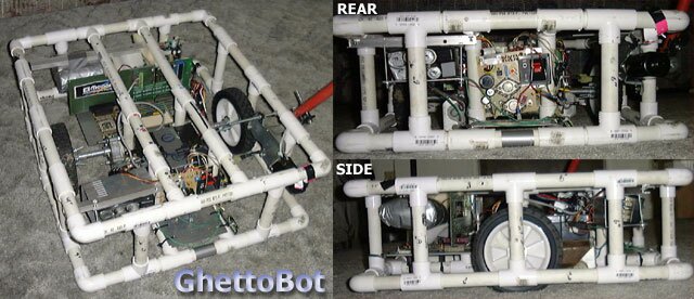
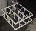
| Overview | The GhettoBot is a battlebot measuring around 2 feet to a side, and around 9" high. The frame is made of 3/4" PVC (water pipes). It was intended to be entered as a light-weight in BattleBots. |
| Why PVC? | PVC was chosen primarily because we are computer people, not mechanical people. We needed something we could work with with the limited tools we had. We didn't have any welding equipment, and we knew the design would be changing a lot as we went. The great thing about PVC is that it can be replaced with steel pipes without much trouble. |
| Won't it break? | Yes. Fortunately, an innovative armor design should provide all the protection we need. Keep in mind that this is a lightweight bot, so the forces attacking won't be very much. |
| What about armor? | Though the bot was retired before the armor was built, here is the idea: The armor is mounted on springs which are attached to the frame. The strength of the springs is just barely enough to keep the armor off the ground (around 2"). When an attack comes from the top, the springs compress which drives the entire shell to the floor. Once the armor is on the floor (which is before the springs completely contract) the force of the attack is transfered to the floor through the primary supports in the armor. Thus, the attackers force never actually contacts the weak PVC frame. |
| Why a Laptop? | Most battlebots are just glorified RC cars. They use off-the-shelf speed controllers, and stock RC controllers. Unfortunately, this makes them impossible to drive. This makes for a lot of robots that can never aim well enough to hit their opponents. Therefore, we chose to go with a computer controlled robot so that we could fix these problems with software. Oh, we also didn't have the $400 for the RC speed controller... Also, keep in mind that we are computer engineers and we love digital stuff :) |
| How long? | Development time was spread out over a 9 month period, but the actual work only took about 2. One for the frame, and one for the control. Add another one for testing and maturing too which we didn't get to. Most of the time was in the evenings after going to school and work all day. |
| The cost? | I think we spent around $100. The motors costed $50 from a junk yard (extremely overpriced). The PVC was really cheap, the weapon motor was free. The motherboard was free, the hard drive was around $7 off ebay. The controller card is worth a lot, but since I made it myself that counts as free. The laptop which controlled the bot was borrowed. The batteries were free. The most expensive part was the wireless LAN Cards, but those were bought for a different project and thus didn't fall into the cost of the bot... So, with a lot of free hardware the cost was really low! |
| Onboard computer? | Yep! This is a 486DX2/66 running Windows 98 on a 340 meg laptop hard drive. I got two identical, full systems (no case, no monitor, no HD) from work where they were just sitting around waiting to be thrown away, so we had a drop-in replacement available. The great thing about the computer onboard is that everything is so standard. If we popped the HD controller then we could have found any computer store and replaced it without any trouble. The only custom part was the controller card which could have been repaired if broken. |
| Worthwhile? | This was a great project. Though it never saw a fight, we learned so much about how to do things that it was definately worth it. Just being able to run a 486 mounted on a combat robot running on batteries on a power supply board I had built was great! |
| What's next? | Check out the future page. There are definately more bots to come! |
| More Info! | This project is completely open, check out GhettoBot Design for the technical stuff! |
The project - An essay on the lifetime of the project
The frame is made of PVC pipe because it is cheap and light. We wanted something that we could easily work with out of our garage and that could be easily modified. The PVC is really cheap and allows us a chance to make changes to the design really easily.
Everything gets attached to the frame, if the frame gets in the way of a component than we change the frame :) For example, the motherboard didn't have enough room in the old frame design, so we took out a few internal supports and now it fits.
The wheels are 8" plasic (hard rubber tires) with 1/2" axels. We had to use some modified schwin pedals to act as the connection between the wheels and the motors.
The wheel motors are off an old Chrysler. They're the power-window motors. They have a worm drive inside which steps down the rpms. It's inefficient, but it works and we don't have to worry about chains or belts or anything.
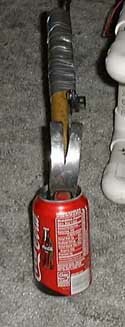
The weapon motor is off a Honda CRX. It is the rear-windshield wiper motor. By design it has a reciprocating motion (for the wiper). We chose to use this motion rather than re-engineer the whole motor case. So now we have a weapon that hits in one direction, reverses itself, and hits again without changing the current applied to it. The actual weapon is a hammer attached to the motor arm which gives it a length of around three feet.
From the very beginning we decided to not use the standard RC controllers for our bot. First off, we didn't have the $400 for a speed controller, and second we wanted to do something different. Over the summer Travis has built an ISA card for the computer which had 24 I/O lines that could be controlled by software. We weren't sure if we could pull it off, but it seemed like a good place to start.
Around November, we had the frame done and the motors and wheels mounted. It could drive around but there was no control at all. It got cold in the garage and the bot sat there until April.
Come April, Travis finally pulled out the bot again and started working on it. After raiding the junkyard for 20A relays, the first thing he did was take apart the old RC airplane that had been broken during a party. He pulled out the RC components (three servos) and built a poor-mans speed controller. Basically, there was a wire on the control arm and two other wires stickin up out of the frame. When the servo rotated it connected the circuit which tripped the relays which turned on the motors. Carin exclaimed "That's so ghetto!" and the name stuck: GhettoBot.
Two days later the ghetto controller was removed from the system. It was replaced with the newest creation: the ISA robot controller. Based on the design Travis had made over the summer (which had since been lost) the new card provided 8 motor outputs, 8 weapon outputs, and 8 sensor inputs all on one card. The card was to fit onto an onboard 486 motherboard which Travis had gotten free from work. Days of wire-wrapping and soldering later the system was ready for a test. The system relied on six relays to provide forward, forward fast, backward, and left and right motion. Through a design choice, if certain relays were closed at the same time the system could short itself out, so care had to be taken when issuing commands to not do that!
The system worked after a bit of tweaking. The first design used optoisolators to drive the relays. That didn't work. Apparently, optoisolators rated for 60mA don't like it when you try to push 170mA through them... The next attempt was to use a smaller relay connected to the optoisolator to drive the larger relay. This worked, but it was clunky and needed a lot of circuitry. Then came Lorin's brainstorm: use a darlington array like we had on our junior project! He went and found an extra one from JP and brought it over. Travis redesigned the circuit to use it -- it replaced both the small relays and the optoisolators -- and we tried it out. It worked beautifully! It could handle 170mA on all 8 channels with no problems at all. We had our design.
The next big steps were changing the wiring systems so that there were actual permanent wires and good connectors on everything. Up until now we were using aligator clips and test leads to get the system running. Wiring harnesses were made for the batteries and relays, filter capacitors were added to the batteries, and a relay-override toggle switch was added for safety.
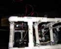
So now we had a bot with on-board relay control coming off the motherboard. The bot looked like it was on life-support with all the wires poking out of it: the keyboard and mouse, the monitor, and power cord, the network cable, the power supply and hard drives taped to the top. It was seriously ghetto again.
A very important part was to create the remote control system. The plan had been to use Travis's wirelss LAN cards from hissenior project which was no longer needed to allow a laptop to control the bot. Unfortunately, nobody knew how to do that.
The first attempts were to establish communication across the network from the control computer to the bot. This was done by using the winsock control in Visual Basic 6. The firsts tests simply sent messages back and forth and after a couple hours tweaking was successful. The next step was to create a control interface
The Pictures
|
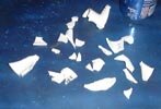
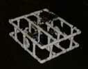
During structural testing for the PVC, we hit a column with a rubber mallet. The joint shattered (the hard plastic) and hit every wall in the garage!
1280x1024, 174k |
|
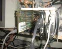
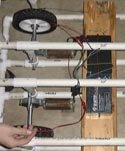
This is the initial control board which was stolen. This is the test setup, with it controlling the stepper motor at top.
1280x1024, 168k |
|
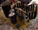
The other side of the card. The big chip is the 82C55. The one's at the upper right are the optoisolators.
1280x1024, 202k |
|
Our first idea was to use a chain drive to step up the speed to the wheels. The sprocket is attached to the motor.
1280x1024, 164k |
|
|
Our work area. Lots of room with nothing nearby to break :)
1280x1024, 154k |
|
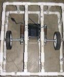
Wheel testing, the batteries were held onto the board to keep them from falling off.
1280x1024, 208k |
|
The first design had the wheels in the back. The front wheel here just skidded around while turning.
1280x1024, 147k |
|
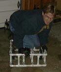
Rob holding the bot while testing on the ping pong table.
1280x1024, 201k |
|
|
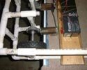
The motors are powered directly off the batteries here, no remote control at all.
1280x1024, 169k |
|
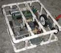
We decided to move the wheels to the center, and the batteries too. The bot is a lot more balanced now.
1280x1024, 152k |
|
These motors are powerful enough to give us a ride around the garage. We couldn't steer, but it went really fast in a straight line!
1280x1024, 145k |
|
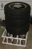
We had some autocross tires sitting around, here they are being transported around by the 'bot.
1280x1024, 156k |
|
This is how the GhettoBot got its name. The GhettoController. A bunch of wires connected to servos that go to relays. Very ghetto.
1280x1024, 145k |
|
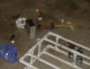
The first night of remote control! It was pushing those garbage cans around in the snow. One time it got a bit out of control and nearly took out my car!
1280x1024, 95k |
|
A front view of the bot, including the relays for the GhettoController.
1280x1024, 86k |
|
Lots of snow, but not enough to short anything out.
1280x1024, 67k |
|
The first attachment of the weapon, we had to test the flying ability of the wireguy!
1280x1024, 191k |
|
|
This can was the poor subject of a power test. It punche through the top easily enough, especially since the arm is a windshield wiper arm off Rob's CRX.
1280x1024, 187k |

|
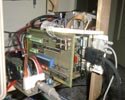
The first test of the motherboard. The relays are held in with duct tape.
1280x1024, 168k |
|
Oblique view, the test code is on the monitor.
1280x1024, 140k |
|
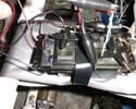
A good view of the weapon arm. The motor is the rear wiper off the CRX.
1280x1024, 144k |
|
This is what happens when you hook the batteries up backwards. A big bang, lots of smoke, and a blown cap.
1280x1024, 140k |

|
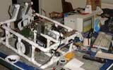
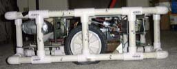
A much more refined bot. Relay armor, a new control card, good stuff. The mud on the wheel was from the offroad tests...
1280x1024, 183k |
|
This is what happens when you don't use fuses. Something starts to smoke... Fortunately, it was repairable and nothing expensive broke!
1600x1200, 354k |
|
The retirement pictures... Everything on the bot is complete and works, except it draws too much power.
1280x1024, 210k |

|
Retirement.
1280x1024, 176k |
|
Greate view of the underside armor. Lots of extra weight but it protects the important parts.
1280x1024, 151k |
|
|
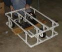
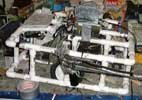
Side view, the wheels are centered and the bot is nearly balanced.
1280x1024, 146k |
|
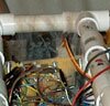
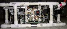
The view from the back, showing the power board and the relay nest.
1280x1024, 164k |
| Site by Kallahar - |