|
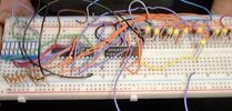
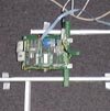
The first prototype for the LED feedback LEDs.
1280x1024, 171k
|
|
|
Lorin shelling out some more money for parts (actually, I think this time it was for food...)
1280x1024, 123k
|
|
This is Lorin during our design review. At this time we had a little remote control running off a function generator which got the bot to scurry across the floor.
1280x1024, 156k
|
|
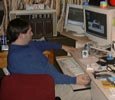
In our first tests we had the bot running off the development board on the desk. There was too much signal noise so we had to scrap that idea pretty quickly...
1280x1024, 179k
|
|
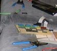
It took a while to get the maze made, so our first runs used stacks of microchips with white tape on top which were duct taped to the floor.
1280x1024, 257k
|
|
An overhead view of the first protomaze. The white cable is the download cable coming off the computer. This made reprogramming the bot really easy.
1280x1024, 234k
|
|
This is another view of our work area. The board on the couch was Rob's junior project which was a RPM/shift indicator for a car.
1280x1024, 215k
|

|
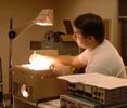
This is Travis doing some 8051 assembly coding.
1280x1024, 177k
|
|
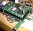
This is an early version, no extra chips, probably no wiring underneath either.
1280x1024, 287k
|
|
Here's Lorin hard at work. Wait, is that a picture of a turbo Omni?
1280x1024, 246k
|
|
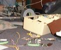
This is the bot in pieces. It looks like it is nearly done. In the background you can see one of the schematics we made.
1280x1024, 178k
|
|
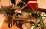
This is a really good view of the IR LEDs. You can also see the plexiglass insulation layer which protected the circuit below from our wirewrap sockets.
1280x1024, 221k
|
|
Diagram: This front view shows all the components together and assembled.
1280x1024, 304k
|
|
|
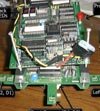
Diagram: The motor controller board. The chips are mostly darlington arrays and diode sets. Yes, stepper is spelled wrong (what, no spell check in photoshop?)
1280x1024, 330k
|
|
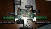
Diagram: The sensor board is just for the LEDs. One of the chips we cooked was the 12V Regulator.
1280x1024, 233k
|
|
|
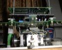
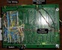
Diagram: The top board was an New Micros 8051 development board. The space on the right is where we put our feedback circuits and the motor connectors.
1280x1024, 264k
|
|
Diagram: I lot of wire wrapping was needed to hook up all the feedback circuit. Fortunately, the development board had enough room (just barely)
1280x1024, 338k
|
|
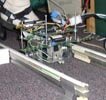
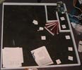
A week before the project was due we finally got the maze together. This is the first test section where we were testing the ability to detect dead ends. All the walls were sitting there loose so the bot couldn't even nudge a wall.
1024x1280, 191k
|