THE MICROPANZER
AN AUTONOMOUS TACTICAL MAZE SOLUTION VEHICLE
Revision 3.5 (April 2000)

Project Team Special Thanks
Travis Puderbaugh
Lorin Mueller
Lee Wetherel
Nathan Hansen
Robert Veitenhans
Mike Mason
Josh Salaets
Carin Zimmer
Martin Urizar
Scott Cannon
Richard King
Doug Lynn
Don Metzler
Claude Kansaku

Section/Contents
1.0 - Introduction & Overview
1.1 - Physical Description
1.2 - Narrative
2.0 - Block Diagrams
2.1 - Software Block Diagram (Simplified)
2.2 - Section Descriptions
3.0 - Main Board
3.1 - External Memory System
4.0 - Motor Controller
5.0 - Sensor Controller
5.1 - Sensor Code Sample
5.2 - Sensor Circuit Diagram
6.0 - Feedback LED Display
6.1 - Feedback 7seg Display
7.0 - Powerup
8.0 - Charging Batteries
8.1 - Power Regulator
9.0 - Software Overview
9.1 - Maze Algorithms

Appendices
A.1 - Software Block Diagram
A.2 - Complete source code
A.3 - Seven segment pld code
A.4 - Sensor display pld code
A.5 - Bus controller pld code
A.6 - Maze specifications
A.7 - Mouse specifications


1.0 - Introduction & Overview

The MicroPanzer is a small battery operated mobile robot that can solve an unknown maze without outside help. The maze has to conform to the guidelines included in an appendix here, which are the standard international rules. It uses infrared sensors, stepper motors, and a microcontroller brain to accomplish this task. After finding the end (goal) of the maze, an optimal path is determined and a speed-run performed. By utilizing the power of the 8051 family of microcontrollers we were able to create the needed circuitry using only a few software-programmable components.

The MicroPanzer is designed to operate in a confined and unknown environment, that is a labyrinth. Therefore, the primary requirements of the Panzer are:

The hardware design is based on three principles, namely ease of assembly, reliability in circuit design, and simplicity of operation.

The robot hardware is divided into three major circuits to meet the requirements. They are the robot microcontroller, the sensor transceiver and the motor driver. The motor controller board, the sensor board, and the 8051 portion of the main board are fabricated on a printed circuit board (PCB). The microcontroller board is a New Micros development board with added hardware, mostly for debugging purposes. The block diagram shows the interconnection of these parts. Each of these sections is described in detail further in this document.

The peripheral circuits on the microcontroller board include the sensor leds and the 7 segment leds, as well as the bus controller pld needed to run the sensors and all of the leds. A serial interface is integrated into the New Micros development board for downloading software from the PC to the onboard RAM. The memory capacity on board is 8K-byte RAM. There is one push-button switch available for the user to program their applications, we used it as a start/stop switch.


1.1 - Physical Description

The MicroPanzer has two drive wheels plus two balancing castor wheels. The drive wheels are connected directly to two stepper motors. The castor wheels, which are located one at the front and one at the back, have 360o of free motion.

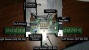
The sensors are organized in a large T that overhangs the walls. The sensors are integrated IR transmitter/receiver packages soldered directly to the PCB.

The only interface the user has with the system is a single multi-purpose button mounted on the main circuit board. It is currently used as a start/stop button to tell the MicroPanzer when to start its run or to start the code over, but it can be reprogrammed to do anything.  The switch is not interrupt based, however, so the state of the input port pin must be polled to determine the status.

Power comes from two independent sources, a 5V and a 14-18V. For development, an external power supply was used which was then connected directly to the board through an extension cable. This was done to save development time waiting for batteries to charge. In the final version, the extension cord is simply removed and the batteries hooked up to the same connector (through the batteries dedicated power regulator board). The batteries used are two pre-assembled ni-cad packs that deliver the power needed.


1.2 - Narrative & Overview

By Travis Puderbaugh - Apr.13.2000

We learned a great deal about product development on this project. There were a lot of obstacles that we encountered that had to be surmounted and that were critical to our success. The first problems were with the design. The first development board we used was the same one we used in the 8051 class. This was our first mistake. We knew from the start that we had to have memory mapped IO devices to read from the sensors and to write to the various feedback leds. Unfortunately, we later learned that the development board we had was already using all the available memory space, leaving no room for our memory mapped IO. Thus came the first redesign, which happened about three weeks before the whole project was supposed to be done. We tossed the old design in favor of a new approach using the newly available New Micros 8051 Development board. This new, sleek, board didn’t have all the fancy features of the old board, and it had memory space available for our memory mapped IO. We kept the same pinouts, and the code to use the sensors, motors, and leds stayed mostly constant, which meant that the code we had already written on the old system could be directly transferred to the new circuit.

Changing development systems came with its own problems, however. Nobody on staff had actually taught a class with the boards, so we were pretty much on our own when it came to getting help on how to use it all. We had to make our own data and power cables, as well as figure out baud rates, pinouts, etc. that the manual didn’t express clearly. Another problem with the included manuals was that they had examples and code for programming the board in C, Basic, and Forth, but nothing even mentioning programming it in Assembly which is what we were doing. Through a lot of experimentation we found the compiler and monitor software and were able to get the code up and running.

Thus came the second dilemma, finding out why the software wouldn’t run. We figured that we had to move the code to some offset since the monitor code was at the start of the codespace. We also learned from the manual that 8000h is the start of ‘user codespace’. We had to find out through experimentation that 8000h – 802Fh is the interrupt locations for the user programs! Basically the New micros board has a fully functioning 8051 system offset to 8000h. Once that was clarified, and our code moved out of the interrupt areas, the old code ran smoothly.

At this point we could turn the motors and drive forward and make 90 degree turns, but we hadn’t even tried to code for the sensors yet. In fact, we hadn’t even tried to hook up the sensor connector yet. So we consulted the design guidelines that we had already laid out for programming the sensors and leds and wrote some test code. We hooked it all up, loaded the test code, and hit run. Nothing happened. My first thought was that something was wired wrong, so I checked over the circuit diagram and realized that the header rows on the schematic weren’t labeled, but the header rows on the sensor board were. So I hooked up the continuity tester and checked the wires. Sure enough, we had gotten the header rows reversed. We had just send 15V through the sensor board’s Vcc lines! Thinking the worst, but hoping for the best, we carefully rewired the sensor header and powered the system back up. It still didn’t work, but it had some activity; the yellow leds all came on, but wouldn’t turn off. So Lorin took a look at the code and realized that we hadn’t updated the memory location that the sensors and leds were responding to since we changed development boards. An easy change was made, we ran down to reburn the pld at 10:00 at night, and we were back in business. The test code worked perfectly.

The next step was to get it all working together. We decided to implement a simple wall following behavior to start. The panzer would follow a wall until it hit its front sensor. It would then check all the sensors and determine which irection had an opening. If none were open it would turn around. The code was fairly simple to write, but there was a lot of it. I had to code all the drift-correction routines, as well as the overall movement. Everything was coded using constants so adjustments to loop times, etc. were easily made.

Lacking information about how the sensor board was intended to be used, we weren’t sure if we were going to be able to poll all the IR sensors at once, or if we had to poll one half at a time. There were pins available to read them separately, or we could tie them together to read them both at once. We chose to read them separately, which meant that the motor clocks had to be tied together since there weren’t enough pins to do both. Thus we could not shut off a single motor at a time, we could only control direction. So we had to reverse the direction of a motor for a single cycle to perform drift correction. It made for jumpy movement, but it worked.

Moving on, we got all the wall following working perfectly, we set up a really tight maze and ran the panzer at full speed. It made it through three times before it clipped a wall. We were very proud, all the code worked great! Unfortunately, later that night we cooked the sensor board’s bus transceiver by having the sensors on for too long (we worked on it for too long one day). Fortunately the bookstore had a replacement chip since it’s just a common bus latch. We weren’t positive that would fix it, but it did so we rejoiced. While waiting for that chip, I started converting the pseudo-coded mapping and maze-solution algorithms into real assembly code so that when it was working again we could integrate the new code easily.

Once that chip was replaced, we could start the mapping development. The first code to be integrated was the map location algorithms since those determined the memory locations that the rest of the algorithms would call. Most of the work in getting this function to work went into calibrating the distance between cells. We eventually abandoned simple tweaking and I spent several laborious hours writing a routine that would only increment the map location if the panzer had traversed at least a third of a square. This would fix the problem it was having ‘jumping’ when the front sensor hit which was incrementing the map several times before getting a stable signal. It was a really tough feature to add, but made the mapping work flawlessly. We made a big maze with a lot of turns and let it loose and it accurately kept track of where it was through the entire maze.

The next step was a big one, adding memory. The biggest problem with this step was that the memory couldn’t be read to or written from without integrating several features at once into the code. Several problems were introduced that were somehow causing the whole thing to crash. I decided to write a special program that would just try to read and write to the memory locations to find out if we were writing to invalid memory locations or not. The test program would write a number to each memory location, then read them all back and display them on the yellow leds. It worked after some tweaking, but when I introduced the new code back into the main program it still failed to work. After spending several days trying to isolate the problem, we decided that we were at a point where more work wouldn’t result in a better product (without a LOT more work). Therefore we decided to finalize the code that we had, and present. So then next Monday we presented, bringing the maze down to Purvine and letting it run through the maze over and over again. It worked fairly well, and caught the interest of everybody that walked by.

Throughout the entire project we were proud of what we were doing, the whole project was fun and entertaining. The first time we got it to crawl around the floor running on code that we had written was a really proud moment. The biggest problem was management. Without a team leader, the tasks and responsibilities worked themselves out. I was determined to make this whole thing work and be really cool, so I stayed up till 2am every night for two weeks to get it done. Fortunately, Lorin was there with me through the late nights and we could take turns writing code and testing out everything. The problem with electing an official team leader is that different team members are going to contribute different amounts. By doing the work dynamically, Lorin and I did most of the work, but we got it done without conflict and on time.


2.0 - Block Diagram


2.1 - Software Block Diagram (Simplified Version)


(Full version in section A.1)

2.2 - Hardware Section Descriptions


Warning: getimagesize: Unable to open 'micropanzer/rpt_2_2.gif' for reading. in /home/.dacker/quick/kallahar/inc-functions.php on line 49

The MicroPanzer is broken up into six manageable segments:

Section Description
Motor Controller Controls both motors with the following signals:

R-Clock, L-Clock, Enable, R-Direction, L-Direction

The Motor controller is self-contained on its own PCB.

Sensor Controller Enable/Disables the IR sensors, and reads the current values. Sends sensor information to the main controller. Has three wall-detection signals per side, plus two front sensors (only one is actually useful, however). The sensors on the wings are used for wall and drift detection.

The Sensor controller is self-contained on its own PCB.

Power Power is distributed to all systems from two independent sources: one 5V source and one 15V source. Both power signals come in through one standard computer hard drive power connector.
Main Board The main controller is what runs the rest of the systems. All the code is stored in RAM which means that the code must be re-downloaded every time the program is to be run. By burning a ROM with the program on it and putting that in socket 1 the system can be ran directly from startup. All the 8051 components, memory, clock, switches, jumpers, the feedback LEDs and 7seg LEDs, as well as the power connectors are located here.
Feedback LEDs The yellow feedback LEDs are software programmable, and are primarily used to give feedback to the user about the current state of the IR transceivers. They can, however, be reprogrammed to be general purpose.
Feedback 7segs The red 7seg LEDs are software programmable, and are primarily used to give the current map location (in two hex digits). These are also reprogrammable.

3.0 - Mainboard


Section Description
MPU The microcontroller is the basis for the board, it provides all of the necessary outputs for the other sections of the board. We made the decision to use the New Micros development board instead of attempting to create our own complete 8051 ‘brain’. We made this decision because the project simply became too large to complete in the allotted time. By using an existing, working design (and assembly) we were able to reduce the amount of time needed to debug a basic part of the system, as well as increase the reliability of that component.
Bus Latch PLD The 8051 based microcontroller uses a multiplexed bus, requiring the use of an address latch to interface with standard SRAM that uses separate data and address busses. The setup on the MicroPanzer uses a latch on the development board and a HY6264L configuration. The RAM uses 13 address lines and returns 8 bit data. The OE, and WR signals are provided directly from the 8051.
7-Seg LEDs The MicroPanzer has a need to output signals for both informational and debugging purposes, which is done using an 8 bit, two digit 7seg LED display. The 7segment drivers are provided by two 16v8s with a clocked input to clock the 7segment output. The clock is the WR line provided by the chip select 16v8.
Yellow LEDs The sensor display can be output to external display using twelve LEDs (eight individual, four are paired), one LED for each infrared sensor. The LEDs are addressable in the same way the sensors are, that is to say that the two outside LEDs are tied together just as the two outside IR sensors are. These are fed through a 16v8 which both inverts output of the signal to active low and clocks the output. This is again read directly off of the data bus. The clock is sourced from the chip select 16v8.
Chip Select Controller The chip select controller is contained in a 16v8. The controller has inputs of A15, A14, A13, A12, A11, A10, and WR. Given this, it generates timing to control all of the devices.

3.1 - External Memory System

The external memory is integrated onto the New Micros development board. This setup is such that port 0 of the microcontroller is both the data and the lower half of the address bus, using an address latch that is also on the system bus. The upper half of the address space is handled on port 2 of the microcontroller exclusively. The onboard address decoder of the New Micros board only responds up F400, at which point the user can add other external memory mapped devices, such as LEDs and sensors in this case.

An assembly example of how to use the memory system is as follows:

(2.1) Memory Write:

mov a, #h'01 ; test value
mov dptr, #h'c000 ; load memory address into dptr
movx , a ; store value in a to mem location

(2.2) Memory Read:

mov dptr, #h'c000 ; load memory address into dptr
movx a, ; get value into a, move from a to wherever you want


4.0 - Motor Controller

The motors are stepper motors slightly larger than the kind found in 5Ľ” floppy drives. The stepper motors are controlled by L298 and L297 (SGS Thompson) chips that allow the motors to be controlled by the microcontroller by only a couple of signals: ClockL, ClockR, enable, DirectionL, and DirectionR. The enable line is tied to the enable on both motor controller chips. The driver hips are a matched pair and are designed as generic stepper motor drivers. The board uses a 5V input for logic, and an unregulated 15V input for the motor power itself.

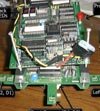
The mobile robot wheels are driven directly by two stepper motors, there is no gearing. Bipolar drivers are used to operate the motors at half-step condition. The bipolar driver has the advantage of delivering about 40% more torque compared to a unipolar driver. Operating at half-step condition will double the linear resolution and the driver also eliminates the low frequency motor resonance that will occur at full-step operations. The driver operates at around 15 volts with the maximum output current at 0.8 Amp per motor.

The bipolar driver operating at half-step condition is formed by a stepping motor sequencer L297 and a dual bridge driver L298N.

The L297 only requires three control signals to operate. There is the step clock, the rotational direction, and the device enable. The half/full step select is tied to Vcc for the half step operation. A chopper circuit for the control of the motor winding current is also built in the L297, and can be adjusted with two onboard potentiometers.

The L298N is a bridge driver to energize the motor windings (L1/L2). Eight fast switching diodes are used to protect the driver output from high reversed discharging voltage across the motor windings.

(Some info courtesy SGS Thompson)


5.0 - Sensor Controller

The sensor controller board is a simple design that uses a ULN2003 darlington type driver to supply a series voltage to two pairs of six IR LEDs. Eight of the IR receivers used a wired “or” setup to supply eight bits of data to a 3 state bus latch/transceiver that can then be memory mapped on the microcontroller board. The board also has a potentiometer that is used to adjust the sensor threshold that is sent to the latch. The sensors tend to have an effective range of about 1 centimeter and perform better at very close ranges. The sensors also prefer a diffuse surface such as flat white paint over a highly reflective surface such as glossy paint. The board also uses a 5V input for logic, and has a 12V onboard regulator fed by the unregulated 15V line to power the IR LEDs in series.

The sensors are memory mapped devices. Therefore the current value of the sensors can be read as if it were standard RAM. The address range is above the U1 and U2 RAM chips that are on the development board. There are eight sensor banks, which are numerically in order with the bytes of the data bus, such as:

Sensor U1 = bit 0
Sensor U2 & U3 = bit 1
Sensor U4 = bit 2
Sensor U5 & U6 = bit 3
Sensor U7 = bit 4
Sensor U8 & U9 = bit 5
Sensor U10 = bit 6
Sensor U11 & U12 = bit 7

The sensor transceiver board is designed to provide the sensor placement at the strategic positions so that the mobile robot is able to navigate in the maze and capture the maze data reliably.

Twelve infrared transceivers are used for the mobile robot. They are arranged to share 8 sensor inputs to the data acquisition interface. Top sensing technique is applied for picking up maze information. The advantage of using infrared sensors with top sensing is that the driver and the data acquisition circuits are fairly simple.

The infrared transmitters are turned on by a darlington driver using a clock cycle that is generated in the microcontroller board. The infrared receiver is connected via a RC filter and then to the latch where its input threshold level can be adjusted by a trimmer. The schematic diagram of the sensor board is shown in section 5.2.


5.1 - Sensor Code Sample

A sensor read is written as follows:

clr p1.4 ; enable IR emitters

mov r0, #10 ; wait 50us

delay1:

djnz r0, delay1

clr p1.6 ; strobe to get latest data

mov dptr, #S_ADR

movx a, ; read from data latch

mov sensors, a2 ; save sensors state to sensors var

mov r0, #10 ; wait 50us

delay2:

djnz r0, delay2

setb p1.6

setb p1.42 ; disable IR emitters

; write value to LED's

mov dptr, #Y_ADR2 ; yellow led's

mov a, sensors ; load sensor data

xrl a, #h'FF ; invert fordisplay

movx , a2 ; write to LEDs


5.2 - Circuit Diagram - Sensor Board


6.0 - Feedback LED Display

The feedback LED system is actually an I/O device all of its own. This means that

The control of this device must be done entirely in software. It would make sense, however to put the feedback code inline with the sensor read code, for reasonable efficiency. This also makes the feedback the most reliable so that what is shown on the LEDs is actually what the processor read, and not what may have happened a few microseconds earlier.

To write to the LEDs, simply load the value into DPTR and do a movx:

.equ Y_ADR, h'f4002 ; address of yellow LED's (f400-f7ff)

mov dptr, #Y_ADR ; yellow led's

mov a, sensors ; load sensor data (already in the variable)

xrl a, #h'FF ; invert for display

movx , a2 ; write to LEDs

By changing the value of a, the yellow leds can be used to indicate any number of things from errors to debug codes to a fancy wait routine.


6.1 - Feedback 7 Segment Display

The 7 Segment display works exactly the same as the yellow leds, but the value written to them is first run through a 7 segment decoder PLD which formats the output. The code is the exact same, simply change the address to #R_ADR.


7.0 - Mainboard powerup and status initialization

At powerup the monitor software on the development board runs. The maze solution code is then downloaded into the board, and the system told to 'run' starting at 8000h, our program starting location. The code stays in the development board's RAM until power is removed. After reset/powerup these values are as follows:

REGISTER(S) CONTENTS
Program counter 0000H
Accumulator 00H
B register 00H
PSW 00H
SP 07H
DPTR 00H
Ports 0-3 FFH*
IP XX000000B
IE 0X000000B
Timer Registers 00H
SCON 00H
SBUF 00H
PCON (CMOS) 0XXX0000B

*- This setup ensures that any devices driving the data bus will not damage the input pins on the 8051. This also causes the motors to default to “on” which creates a hissing noise. It is preferable to disable the motor pin as soon as possible to prevent motor overheating.

Program execution will begin at address 0000H, as expected, which will start the monitor code allowing us to download our program into the development board starting at address 8000h. Once our code starts running (by entering X8000 in the monitor terminal), the monitor code is never called, it is only used for loading the code initially. This makes it a lot easier to develop on since we don't have to worry about the monitor needing memory, timers, or anything else.

The Development Board has its monitor code at the lower memory locations, so all our programs and data must start at 8000h.


8.0 - Charging Batteries

Using a power supply that has both a current limiting and voltage limiting adjustments such as the Acopian Regulated Power Supply Model K32S60, ADJUST ALL SETTINGS TO ZERO BEFORE TURNING IT ON. Connect the terminals of the battery pack to the power supply such that the ground terminal of the battery pack is attached to the ground terminal of the power supply and the positive terminals are connected to each other. Turn power supply on. Slowly increase the current and voltage limiters, being careful not to exceed 200 mA of current and the voltage is limited to the appropriate voltage (9V for small pack and 18V for larger pack).

The charging current will eventually decrease make sure that the limited voltage is still at appropriate levels, adjusting as needed. It is normal after time has passed, up to several hours, for the charging voltage to be at appropriate levels and the charging current decreased to zero even though the current limiter is opened all the way. It is at this point that the battery pack is completely charged.


8.1 - Power Regulator Schematic

The 5V power coming from the batteries must be regulated! There is no on-board filtering or protection on any of the boards. All power concerns must be addressed before the power gets to the connector. When running on the power cord from the regulated external supply this is not a problem, but when running on batteries this becomes a critical step. The 15V line does not need to be regulated since it runs directly to the motors. The sensors use the 15V line as well but they have a 12V regulator.


9.0 - Software Overview

The software was implemented gradually in three stages. The fist step was to enable the mouse to move forward , and perform left, right and U-turn without reading from the sensors. Next step was to perform the "tunnel run", meaning that it had to transverse through a straight path by reading from the sensors and perform a turn at the end successfully. The "tunnel run" flowchart explains the above function. At last a flow chart for the final software is shown in the "general navigation plan" section. It is a one hand on the wall algorithm easily modified for either left or right hand wall following. The final stage is to use an algorithm such as Lee's Algorithm, outlined later, which is used to determine the shortest and fastest path through the maze.


9.1 - Maze Algorithms

There are many approaches that can be taken toward maze solution. We used two different ones. The first, One Hand on the Wall, was simple to do and was a good test to make sure that all the sensors and motors and such were working correctly. After that one was working well we could proceed to more advanced software, namely Lee’s Algorithm (not the Lee in our group) which is a very good algorithm.

One Hand on the Wall

This is the simplest approach to maze solving, but unfortunately it only works for a certain class of mazes that any competition maze doesn’t follow. No mapping is done, and a ‘speed run’ is impossible. You do not need to be able to see where all the walls are, you simply move so that there is always a wall on one side of you. For example, if you kept your hand on the wall in the maze shown in figure M.1 , you would follow the illustrated path to the center. Figure M.2 illustrates a maze that cannot be solved using this algorithm. Even though the robot kept one ‘hand’ on a wall the whole time, it simply ended up back at the start without ever reaching the center goal. Our first aim was to implement this algorithm, in order to tune it fine during its navigation in the maze, and then to proceed implementing an optimal maze solving algorithm as described next.

Lee’s Algorithm

This method does an exhaustive search of all possible paths from a start position to a finish (target) position. It always finds a route, if there is one, and it will find the shortest route. It relies on having a "map" of the maze in memory, which must be built by looking at the walls as the robot progresses through the maze. Implementing Lee’s Algorithm consists of two phases, described below. Note that this part of the algorithm gets run after the robot has located the center of the maze. This algorithm doesn’t help the mouse find the center, it calculates the best path for the speed run.

Numbering the squares

Number the target point(s) 0. Now number any points which can be reached in one step from the target with 1, without overwriting any zeros (figure M3). Continue numbering squares accessible from the 1’s with 2, etc. until the start square is numbered. If the start square does not get numbered, and no further squares can be reached, the there is no path at all. Figure M4 shows the numbering complete.

Trace Path Through Descending Numbers

From the start position, move to a square with a number one less. Continue doing this until you reach the target (numbered 0). There may be more than one possible route, but if so they will all be of equal length. In figure M5, there is only one route with descending numbers, so this is the shortest. This part of the algorithm could be enhanced to give preference to long, straight runs because the robot can traverse those faster, even though they may be the same number of squares to the center.

Implementation of Lee’s algorithm requires two arrays: one for the Lee numbers and the other for the map, which records where the walls are in the maze. The Lee array contains integer numbers that represent the minimum number of squares required to travel between the current square and the target. The map array contains bytes where a bit is used to represent the presence or the absence of a wall in each of the four directions N, S, E, W. The MSB is used to identify if the square has been visited before. When making decisions as to which way to go, the processor uses information from both arrays: the mouse moves to the adjacent square that has the lowest Lee number, which should be one less than the current value. In terms of memory capacity that is required to store these arrays the following calculations were made. The maze is 16x16 cells, so 256 locations are required for each array. The largest possible Lee number is 256-4 (the target squares)=252, which can be recorded in a byte. For the map, only 4 bits are required for the walls and the MSB can be used to identify if the square has been visited before, giving 5 bits in total, so again we use bytes. Therefore the total memory required is 512 bytes.

Unfortunately, Lee's Algorithm remains on the idea block as we were unable to implement it in time. This was a great disappointment, but I'm sure that anyone who follows in our footsteps (and learns from our mistakes) will have better luck.


A.1 - Software Block Diagrams

A.1 - Main Section

A.1 - Move Forward Routine

A.1 - Turning Routines

A.1 - Sensor & 180o Routines


A.2 - Complete Source Code

;-------------------------------------------------------------------------------
; Travis Puderbaugh - Mar.2000
; printing note: tab size is set at 10 **
;-------------------------------------------------------------------------------
; move forward two squares, turn right, loop forever.
; p1.0 = Motor: Right Motor Clock
; p1.1 = Motor: Master Enable
; p1.2 = Motor: Left motor direction (1 = forward)
; p1.3 = Motor: Right motor direction (1 = forward)
; p1.4 = Sensor: IR Emitters Enable
; p1.5 = Red Switch (active low)
; p1.6 = Sensor: Clock (Strobes IR emitters)
; p1.7 = Motor: Left Motor Clock
;-------------------------------------------------------------------------------
.code
.org 8000h
ljmp start
.org h'800B
ljmp int_tf0
.equ NUMLOOP_F, 43   ; number of times to run the move forward loop
.equ NUMLOOP_T, 13   ; number of times to run the turn loops
.equ NUMSTEPS_F, 8   ; number of steps to go forward
.equ NUMSTEPS_1cm, 55   ; number of steps to go forward one cm
.equ NUMSTEPS_GAP, h'ee ; number of steps to go forward after open detect
.equ NUMSTEPS_T,18  ; number of steps to make a turn
.equ MIN_DELAY_U, -2   ; minimum delay (fastest motor speed) (upper byte)
.equ MIN_DELAY_L,0    ; minimum delay (fastest motor speed) (lower byte)
.equ MIN_DELAY_UT, -2  ; minimum delay (fastest motor speed) (upper byte)
.equ MIN_DELAY_LT, 0   ; minimum delay (fastest motor speed) (lower byte)
.equ MAZE_X, h'06       ; size of maze in x units
.equ MAZE_Y, h'06      ; size of maze in y units
.equ MAZE_GOAL, h'55   ; goal units (start in lower left at 0,0)
.equ ar0, h'00    ; register 0
.equ ar1, h'01    ; register 1
.equ ar2, h'02    ; register 2
.equ ar3, h'03    ; register 3
.equ ar4, h'04    ; register 3
.equ ar5, h'05    ; register 3
.equ numsteps, h'18     ; bank 3 - number of steps taken in loop
.equ sensors, h'19 ; bank 3 - last value of sensors
.equ location, h'1a  ; bank 3 - hex location of mouse in maze
.equ map_mem_loc, h'1b  ; bank 3 - memory location of current map loc
.equ wall_count , h'1c  ; bank 3 - end wall counter for detect
.equ direction , h'1d  ; bitram - current direction being faced
.equ mclk_left , h'20 ; bitram - 1 for clock on
.equ mclk_right , h'21  ; bitram - 1 for clock on
.equ fullwave, h'22  ; bitram - toggles for full wave clock pulses
.equ map_doupdate,h'23  ; bitram - status bit of map stuff
.equ gap_detect , h'24  ; bitram - status bit of gap detect
.equ gap_bit1, h'25 ; bitram - status bit of gap 1
.equ Y_ADR, h'f400     ; address of yellow LED's (f400-f7ff)
.equ S_ADR, h'fc00 ; sensor stuff (fc00-ffff)
.equ R_ADR, h'f800     ; address of red 7seg's (f800-fbff)
.equ MAP, h'c000        ; dev board code ram, add location to this
.org 8100h

;-------------------------------------------------------------------------------
; int_tf0 - toggles p1.0 and p1.7 (depending on motor_dirs bits 0 and 1), the
; motor clock bit, checks delay to make sure > min also decrements numsteps to
; know how many steps have been taken.
;-------------------------------------------------------------------------------
int_tf0:
jb fullwave, skip1      ; keeps track of full wave
dec numsteps         ; count down number of steps taken
skip1:
cpl fullwave           ; toggle fullwave bit
jnb mclk_left, int_skip1  ; if mclk_left = 0, skip toggle
cpl p1.7                  ; toggle left motor clock bit
int_skip1:
jnb mclk_right, int_skip2 ; if mclk_right = 0, skip toggle
cpl p1.0                 ; toggle right motor clock bit
int_skip2:
jb p1.3, turnfreq
jnb p1.2, turnfreq
mov th0, #MIN_DELAY_U     ; load timer MSB
mov tl0, #MIN_DELAY_L     ; load timer LSB
ljmp normalfreq
turnfreq:
mov th0, #MIN_DELAY_UT    ; load timer MSB
mov tl0, #MIN_DELAY_LT    ; load timer LSB
normalfreq:
reti

;-------------------------------------------------------------------------------
; maincode - main control stuff
;-------------------------------------------------------------------------------
.org 8500h
start:
mov direction, #b'00001000  ; (NESWNESW) start direction as north
setb map_doupdate
clr p1.4                    ; disable IR emitters
clr tr0
lcall delay
clr p1.1                    ; disable motors
;mov location, #h'ff   ; reset location to count down from ffh
;mov map_mem_loc, #0  ; store 0's
;st_loop1            ; zero map
;lcall put_map_mem_loc  ; put zero in here
;djnz location, st_loop1
;lcall put_map_mem_loc  ; pick up last location at 00h
;mov location, #h'00   ; reset location to 00h when done
;start test
;mov location, #h'ff
;mov map_mem_loc, #h'ff
;lcall put_map_mem_loc
;
;
;mov location, #h'ff
;lcall get_map_mem_loc
;
;mov a, map_mem_loc
;mov dptr, #Y_ADR       ; yellow leds
;movx , a
;
;mov a, location
;mov dptr, #R_ADR       ; red 7seg's
;movx , a
;lcall wait
;mov location, #h'00    ; reset location to 00h
; end test
mov location, #h'00     ; reset location to 00h when done
lcall waittostart       ; wait till start button pressed
setb p1.4                ; enable IR emitters
lcall delay              ; final delay before it get's going
lcall delay
lcall delay
lcall delay
lcall init_timers       ; set up timers for correct modes
setb p1.1                ; enable motors
lcall check_sensors
setb mclk_left        ; enable left clock
setb mclk_right      ; enable right clock
mainloop:
;; lcall check_sensors   ; sensor test code! (comment out on real)
;; ljmp mainloop         ; sensor test code!
mov dptr, #R_ADR        ; red 7seg's
mov a, location
movx , a
lcall move_forward
; move_forward kicks out when:
; a) it hits a wall head-on
; b) it has moved one square (by distance)
; hitting the wall makes it more accurate because it gives a reference point.
lcall check_sensors      ; get current sensor data
mov a, sensors

jb acc.4, main_end    ; if the front one hasn't hit, don't check any
jnb acc.1, s_left
jnb acc.2, s_left
jnb acc.3, s_left
jnb acc.5, s_right
jnb acc.6, s_right
jnb acc.7, s_right
jnb acc.4, s_right
jnb acc.0, s_right
ljmp main_end
s_right: lcall turn_right
ljmp main_end
s_left:  jnb acc.5, s_180
jnb acc.6, s_180
jnb acc.7, s_180
lcall turn_left
ljmp main_end
s_180:  lcall turn_180
ljmp main_end
main_end:
ljmp mainloop
;ljmp start      ; loop forever

;-------------------------------------------------------------------------------
; init_timers - sets up initial modes for motor timers, etc.
;-------------------------------------------------------------------------------
init_timers:
;anl pcon, h'df  ; pcon register set (not really needed on NMI)
mov a, tmod          ; get timer mode
orl a, #00000001b        ; set timer bits
anl a, #11110001b        ; set more timer bits
mov tmod, a          ; t0: 16 bit one-shot
setb ea                   ; enable all interrupts (condition to masking)
setb et0                  ; enable timer0 overflow interrupt, TF0 = 000Bh
setb pt0                  ; timer 0 priority
mov th0, #MIN_DELAY_U    ; load timer msb
mov tl0, #MIN_DELAY_L    ; load timer lsb

ret                       ; return

;-------------------------------------------------------------------------------
; check_sensors - reads the sensors, writes them out to the yellow led's
;-------------------------------------------------------------------------------
check_sensors:
; read both led sides
push ar0
clr p1.4                  ; enable IR emitters
mov r0, #10           ; wait 50us
delay1:  djnz r0, delay1
clr p1.6                  ; strobe to get latest data
mov dptr, #S_ADR
movx a,         ; read from data latch
mov sensors, a       ; save sensors state to sensors var
mov r0, #10           ; wait 50us
delay2:  djnz r0, delay2
setb p1.6
setb p1.4                  ; disable IR emitters
; write value to LED's
mov dptr, #Y_ADR        ; yellow led's
mov a, sensors      ; load sensor data
xrl a, #h'FF            ; invert for display
;mov a, direction   ; test code, display dir on yellows
movx , a         ; write to LEDs
pop ar0
ret

;-------------------------------------------------------------------------------
; move_forward - moves forward one square, stops if front sensor hits.
;-------------------------------------------------------------------------------
move_forward:
push ar0
push ar1
setb p1.2                  ; left motor forward
clr p1.3                  ; right motor forward
mov wall_count, #0
mov r1, #NUMLOOP_F        ; number of times to loop this routine
f_loop1:
mov numsteps, #NUMSTEPS_F ; loop NUMSTEPS_F times
setb tr0              ; start motor clock (delay)
m_forward_loop:
mov r0, numsteps
lcall check_sensors        ; get current sensor data
lcall check_forward        ; anti-wall collision stuff
jb p1.5, nostopbutton1    ; skip jump out if p1.5 not pressed
ljmp start
nostopbutton1:
cjne r0, #0, m_forward_loop; loop till count is zero
lcall check_sensors        ; get current sensor data
lcall drift_correct        ; drift correction
mov a, sensors
jnb acc.1, no_right_gap ; if 1, 2, or 3 are not set, then
jnb acc.2, no_right_gap ; there is no right wall.
jnb acc.3, no_right_gap
inc wall_count
mov r6, wall_count
cjne r6, #h'9, no_right_gap_skip
;ljmp no_right_gap_skip
gap_skip:
;jnb acc.5, left_wall_present ; if 5, 6, or 7 are not set, then
;jnb acc.6, left_wall_present ; there is no left wall.. REALISTICALLY
;jnb acc.7, left_wall_present ; this should NOT happen unless at a cross intersection
;ljmp no_right_gap             ; but if it does, go to normal straight
left_wall_present:
mov r0, #0             ; satisfy end of move_forward loop
mov r1, #1             ; satisfy end of move_forward loop
;setb gap_detect      ; gap bit set
lcall move_forward_gap  ; call move to center of next square
lcall turn_right        ; turn
ljmp f_end1

no_right_gap:
mov wall_count, #0
no_right_gap_skip:

dec r1
cjne r1, #0, f_loop1   ; number of times to loop this routine
f_end1:  clr tr0       ; stop timer
lcall update_map        ; update map, direction
pop ar1
pop ar0
ret

;-------------------------------------------------------------------------------
; check_forward: stops forward motion on hits
;-------------------------------------------------------------------------------
check_forward:
push ar4
setb map_doupdate
mov a, sensors
jb acc.4, cf_endall    ; if d4(front sensor) isn't hit, skip exit
mov r4, #NUMLOOP_F / 2 ; must move at least half a square for it to count
mov a, r1
subb a, r4 ; (r1 - (numloop_f/2))
jc   cf_skip            ; if > half way, don't skip position ignore
clr map_doupdate
cf_skip:
mov r0, #0             ; satisfy end of move_forward loop
mov r1, #1             ; satisfy end of move_forward loop

cf_endall:
pop ar4
ret

;;; special note: DO NOT POP r0, r1! It's intentional to overwrite them!
;-------------------------------------------------------------------------------
; drift_correct: corrects for drift, stops on bad things
;-------------------------------------------------------------------------------
drift_correct:
push ar0
push ar1
mov a, sensors
jnb acc.4, dr_endS     ; if d4(front sensor) hits, exit move_forward
; (D7 & D6) ? Hold L
; (D7 & D6') ? Hold L, Hold L
; (D1 & D2) ? Hold L
; (D1 & D2') ? Hold L, Hold L
; (D5 & D6) ? Hold R
; (D5 & D6') ? Hold R, Hold R
; (D3 & D2) ? Hold R
; (D3 & D2') ? Hold R, Hold R
; if 7, hold L
mov a, sensors
jb   acc.7, dr_skip7
lcall dr_holdL
; if 6', hold L
mov a, sensors
jnb acc.6, dr_skip7
lcall dr_holdL
dr_skip7:
; if 1, hold L
mov a, sensors
jb   acc.1, dr_skip1
lcall dr_holdL
; if 2', hold L
mov a, sensors
jnb acc.2, dr_skip1
lcall dr_holdL
dr_skip1:
; if 5, hold R
mov a, sensors
jb acc.5, dr_skip5
lcall dr_holdR
; if 6', hold R
mov a, sensors
jnb acc.6, dr_skip5
lcall dr_holdR
dr_skip5:
; if 3, hold R
mov a, sensors
jb acc.3, dr_skip3
lcall dr_holdR
; if 2', hold R
mov a, sensors
jnb acc.2, dr_skip3
lcall dr_holdR
dr_skip3:
ljmp dr_endall
dr_endS:
pop ar1
pop ar0
mov r0, #0             ; satisfy end of move_forward loop
mov r1, #1             ; satisfy end of move_forward loop
ret

dr_holdL:
mov b, numsteps
dec b
dr_dlyL0:
mov a, numsteps
cjne a, b, dr_dlyL0
clr mclk_left          ; hold left
mov b, numsteps
;dec b
dec b
dr_dlyL1:
mov a, numsteps
cjne a, b, dr_dlyL1
setb mclk_left         ; restore left
ret
dr_holdR:
mov b, numsteps
dec b
dr_dlyR0:
mov a, numsteps
cjne a, b, dr_dlyR0
clr mclk_right         ; hold right
mov b, numsteps
;dec b
dec b
dr_dlyR1:
mov a, numsteps
cjne a, b, dr_dlyR1
setb mclk_right       ; restore right
ret
dr_endall:
pop ar1
pop ar0
ret

;-------------------------------------------------------------------------------
; move_forward_1cm - moves forward one centimeter
;-------------------------------------------------------------------------------
move_forward_1cm:
push ar0
setb p1.2             ; left motor forward
clr p1.3             ; right motor forward
setb tr0              ; start timer
mov numsteps, #NUMSTEPS_1cm ; loop NUMSTEPS_1cm times
setb tr0              ; start motor clock (delay)
m_forward_loop_1cm:
lcall drift_correct   ; drift correction
mov r0, numsteps
cjne r0, #0, m_forward_loop_1cm ; loop till count is zero
f_end1_1cm:
clr tr0        ; stop timer
pop ar0
ret

;-------------------------------------------------------------------------------
; move_forward_gap - moves forward one centimeter
;-------------------------------------------------------------------------------
move_forward_gap:
push ar0
setb p1.2             ; left motor forward
clr p1.3             ; right motor forward
setb tr0              ; start timer
mov numsteps, #NUMSTEPS_GAP  ; loop NUMSTEPS_GAP times
setb tr0              ; start motor clock (delay)
m_forward_loop_gap:
lcall drift_correct   ; drift correction
mov r0, numsteps
cjne r0, #0, m_forward_loop_gap ; loop till count is zero
f_end1_gap:
clr tr0        ; stop timer
pop ar0
ret

;-------------------------------------------------------------------------------
; turn_right - turns right 90 degrees.
;-------------------------------------------------------------------------------
turn_right:
push ar0
push ar1
mov r4, a
mov a, direction
rr   a                  ; shift right direction
mov direction, a
lcall move_forward_1cm  ; move forward one more cm
;jnb gap_detect, no_go_gap
;jnb gap_bit1, no_second_space
;lcall move_forward_gap
;no_second_space:
;lcall move_forward_gap  ; move forward one more gapspace
;setb gap_bit1
;clr gap_detect
;no_go_gap:
;mov th0, #h'00
;mov tl0, #h'00
clr p1.2                 ; left motor forward
clr p1.3                 ; right motor backward
setb tr0                  ; start timer
mov r1, #NUMLOOP_T       ; number of times to loop this routine
r_loop1:
mov numsteps, #NUMSTEPS_T; number of steps to take
setb tr0                  ; start motor clock
turn_right_loop:
mov r0, numsteps
cjne r0, #0, turn_right_loop ; loop till count is zero
dec r1
cjne r1, #0, r_loop1    ; number of times to loop this routine
r_end1: clr tr0          ; stop timer
pop ar1
pop ar0
ret

;-------------------------------------------------------------------------------
; turn_left - turns left 90 degrees.
;-------------------------------------------------------------------------------
turn_left:
push ar0
push ar1
mov r4, a
mov a, direction
rl   a                    ; shift left direction
mov direction, a
lcall move_forward_1cm  ; move forward one more cm
;mov th0, #h'00
;mov tl0, #h'00
setb p1.2            ; left motor forward
setb p1.3                 ; right motor backward
setb tr0                  ; start timer
mov r1, #NUMLOOP_T       ; number of times to loop this routine
l_loop1:
mov numsteps, #NUMSTEPS_T ; number of steps to take
setb tr0                  ; start motor clock
turn_left_loop:
mov r0, numsteps
cjne r0, #0, turn_left_loop ; loop till count is zero
dec r1
cjne r1, #0, l_loop1     ; number of times to loop this routine
l_end1:  clr tr0        ; stop timer
pop ar1
pop ar0
ret

;-------------------------------------------------------------------------------
; turn_180 - turns left 180 degrees.
;-------------------------------------------------------------------------------
turn_180:
push ar0
push ar1
mov r4, a
mov a, direction
rl a                      ; shift left direction
mov direction, a
lcall move_forward_1cm  ; move forward one more cm
setb p1.2                 ; left motor forward
setb p1.3                 ; right motor backward
setb tr0                  ; start timer
lcall time_90_loop
lcall time_90_loop
a180_end1:   clr tr0     ; stop timer
pop ar1
pop ar0
ret

;-------------------------------------------------------------------------------
; time_90_loop - timing loop for 90 degrees
;-------------------------------------------------------------------------------
time_90_loop:
push ar0
push ar1
mov r1, #NUMLOOP_T       ; number of times to loop this routine
a180_loop1:
mov numsteps, #NUMSTEPS_T ; number of steps to take
setb tr0                   ; start motor clock
turn_180_loop:
mov r0, numsteps
cjne r0, #0, turn_180_loop ; loop till count is zero
dec r1
cjne r1, #0, a180_loop1  ; number of times to loop this routine
pop ar1
pop ar0
ret

;-------------------------------------------------------------------------------
; waittostart - cool 'Kit' bar, waits till keypress
;-------------------------------------------------------------------------------
waittostart:
;; jnb p1.5, delay       ; jump out
;; jnb p1.5, endstart    ; jump out
mov dptr, #Y_ADR
mov a, #b'10000000
movx , a
lcall shortdelay
jnb p1.5, endstart              ; jump out
mov a, #b'01000000
movx , a
lcall shortdelay
jnb p1.5, endstart              ; jump out
mov a, #b'00100000
movx , a
lcall shortdelay
jnb p1.5, endstart              ; jump out
mov a, #b'00010000
movx , a
lcall shortdelay
jnb p1.5, endstart              ; jump out
mov a, #b'00000010
movx , a
lcall shortdelay
jnb p1.5, endstart              ; jump out
mov a, #b'00000100
movx , a
lcall shortdelay
jnb p1.5, endstart              ; jump out
mov a, #b'00001000
movx , a
lcall shortdelay
jnb p1.5, endstart              ; jump out
mov dptr, #Y_ADR
mov a, #b'00001000
movx , a
lcall shortdelay
jnb p1.5, endstart              ; jump out
mov a, #b'00000100
movx , a
lcall shortdelay
jnb p1.5, endstart              ; jump out
mov a, #b'00000010
movx , a
lcall shortdelay
jnb p1.5, endstart              ; jump out
mov a, #b'00000001
movx , a
lcall shortdelay
jnb p1.5, endstart              ; jump out
mov a, #b'00100000
movx , a
lcall shortdelay
jnb p1.5, endstart              ; jump out
mov a, #b'01000000
movx , a
lcall shortdelay
jnb p1.5, endstart              ; jump out
mov a, #b'10000000
movx , a
lcall shortdelay
ljmp waittostart
endstart:
ret
; shortdelay - shorter delay
shortdelay:
push ar1
push ar2
mov r1, #h'66
shortdelayx:  mov r2, #h'ff
shortdelay1:  djnz r2, shortdelay1
              djnz r1, shortdelayx
pop ar2
pop ar1
ret
; delay - short delay
delay:
push ar1
push ar2
mov r1, #h'ff
delayx:
mov r2, #h'ff
delay1y:
djnz r2, delay1y
djnz r1, delayx
pop ar2
pop ar1
ret

;;;;; mapping functions
;-------------------------------------------------------------------------------
; update_map: updates map info
;-------------------------------------------------------------------------------
update_map:
push ar0
jnb map_doupdate, up_end
setb map_doupdate
;mov map_mem_loc, #1        ; mark previous square as visited
;lcall put_map_mem_loc
lcall update_direction  ; update absolute direction bit
mov a, direction
jb acc.3, up_inc_low ; N
jb acc.2, up_inc_high   ; E
jb acc.1, up_dec_low    ; S
jb acc.0, up_dec_high  ; W
ljmp start ; if none, it's lost so stop (should never happen)
up_inc_low:
inc location           ; inc lower byte
ljmp up_end
up_dec_low:
dec location           ; dec lower byte
ljmp up_end
up_inc_high:
mov a, location
add a, #h'10           ; inc upper byte (add 10h)
mov location, a
ljmp up_end
up_dec_high:
mov a, location
subb a, #h'10          ; dec upper byte (sub 10h)
mov location, a
ljmp up_end
up_end:
;lcall get_map_mem_loc  ; get data at current map mem location
;mov a, map_mem_loc    ; move current value to a
;; start test
;mov dptr, #Y_ADR      ; yellow led's
;movx , a        ; write to LEDs
;; end test
;cjne a, #1, up_skip0   ; if traveled area, end maze detection
;ljmp start
;up_skip0:
mov a, location       ; mov current loc into a
cjne a, #MAZE_GOAL, up_skip   ;if at final point, end maze detection.
mov dptr, #R_ADR             ; red 7seg's
mov a, location
movx , a
ljmp start
up_skip:
pop ar0
ret

;-------------------------------------------------------------------------------
; update_direction: updates absolute direction
;-------------------------------------------------------------------------------
update_direction:
mov a, direction
mov c, acc.4
orl c, acc.0            ; W
mov acc.0, c

mov c, acc.7
orl c, acc.3            ; N
mov acc.3, c
mov c, acc.6
orl c, acc.2            ; E
mov acc.2, c
mov c, acc.5
orl c, acc.1            ; S
mov acc.1, c
anl acc, #b'00001111 ; clear upper bits
mov direction, a
ret

;-------------------------------------------------------------------------------
; get_map_mem_loc: moves into map_mem_loc the data at the memory location for
; the current location of the robot.
;-------------------------------------------------------------------------------
get_map_mem_loc:
mov dptr, #MAP          ; load map address into dptr
mov a, dpl
add a, location
mov dpl, a
movx a,         ; get value into a
mov map_mem_loc, a      ; value stored at current map location
ret

;-------------------------------------------------------------------------------
; put_map_mem_loc: stores data in map_mem_loc into current map/memory location.
;-------------------------------------------------------------------------------
put_map_mem_loc:
mov dptr, #MAP          ; load map address into dptr
mov a, dpl
add a, location
mov dpl, a
mov a, map_mem_loc   ; value stored at current map location
movx , a        ; store value in a to mem location
ret

;-------------------------------------------------------------------------------
; wait: wait for keypress, debug only
;-------------------------------------------------------------------------------
wait:
jnb p1.5, endstartx     ; jump out
ljmp wait
endstartx:
lcall delay ; debounce
lcall delay
ret
.end


A.3 - Seven Segment PLD Code

JP, 7 Segment Decoders
| GAL16V8 clock:CLK, 2:D43, 3:D2, 4:D1, 5:D0, 12:A1, 13:A2, 14:A3, 15:A4, 16:A5, 17:A6, 18:A7
| REGISTERS: CLK // A[1..7]
| TABLE: D[0..3] -> A[1..7]
| {
| 0000b -> 0000001b
|   0001b -> 1001111b
|   0010b -> 0010010b
|   0011b -> 0000110b
|   0100b -> 1001100b
|   0101b -> 0100100b
|   0110b -> 0100000b
|   0111b -> 0001111b
|   1000b -> 0000000b
|   1001b -> 0000100b
|   1010b -> 0001000b
|   1011b -> 1100000b
|   1100b -> 0110001b
|   1101b -> 1000010b
|   1110b -> 0110000b
|   1111b -> 0111000b
| }


A.4 - Sensor Display PLD Code

JP, Feedback LEDs
| GAL16V8 clock:CLK, 2:D0, 3:D1, 4:D2, 5:D3, 6:D4, 7:D5, 8:D6, 9:D7 12:A0, 13:A1, 14:A2, 15:A3, 16:A4, 17:A5, 18:A6, 19:A7
| REGISTERS: CLK // A[0..7]
| n = 0..7: A[n]=D[n]'


A.5 - Bus Controller PLD Code

JP, Chipselect / Bus Controller PLD (Sensors Enabled)
| GAL16V8 1:A13, 2:A14, 3:A15, 4:WRP, 5:A10, 6:A11, 7:A12, 12:CSS, 13:WR7, 14:WRF
|
|  ACTIVE-LOW: CSS, WRP
|| FC00-FFFF
| CSS = A10 & A11 & A12 & A13 & A14 & A15 |Chip Select Sensors
|| F800-FBFF
| WR7 = A10' & A11 & A12 & A13 & A14 & A15 & WRP |Write Pulse 7Seg
|| F400-F7FF
| WRF = A10 & A11' & A12 & A13 & A14 & A15 & WRP |Write Pulse Feedback LED


A.6 - Maze Specifications

From 1991 Singapore Competition:

Maze Specifications
1.1 The maze shall comprise 16 x 16 multiples of an 18cm x 18cm unit square. The walls constituting the maze shall be 5cm high and 1.2 cm thick. Passageways between the walls shall be 16.8 cm wide. The outside wall shall enclose the entire maze.
1.2 The sides of the maze walls shall be white, and the top of the walls shall be red. The floor of the maze shall be made of wood and finished with a non-gloss black paint. The coating on the top and sides of the walls shall be selected to reflect infra-red light and the coating on the floor shall absorb it.
1.3 The start of the maze shall be located at one of the four corners. The starting square shall have walls on three sides. The starting square orientation shall be such that when the open wall is to the “north”, outside maze walls are on the “west”, and “south”. At the center of the maze shall be a large opening which is composed of 4 unit squares.  This central square shall be the destination.
1.4 Small square posts, each 1.2 cm x 1.2 cm x 5 cm high, at the four corners of each unit square are called lattice points. The maze shall be constituted such that there is at least one wall touching each lattice point, except for the destination square.
1.5 The dimensions of the maze shall be accurate to within 5% or 2cm, whichever is less. Assembly joints on the maze floor shall not involve steps of greater than 0.5mm. The change of slope at an assembly joint shall not be greater than 4o.  Gaps between the walls of adjacent squares shall not be greater than 1mm.

A.7 - Mouse Specifications

From 1991 Singapore Competition:

Micromouse Specifications
2.1 The length and width of the micromouse shall be restricted to a square region of 25cm x 25cm. The dimensions of a micromouse which changes geometry during a run shall never be greater than 25cm x 25cm. There is no restriction on the height of the micromouse.
2.2 The micromouse must be completely self-contained and must receive no outside help.
2.3 The method of wall sensing is at the discretion of the builder; however, the micromouse must not exert a force on any wall likely to cause damage. The method of propulsion is at the discretion of the builder, provided the power source is non-polluting.
2.4 The micromouse shall not leave anything behind while negotiating the maze.
2.5 A micromouse shall not jump over, climb, scratch, damage, or destroy the walls of the maze.

Site by Kallahar -